In today’s complex energy world, the reactive load in the power grid is constantly increasing. The increase in the power of transformers, transmission lines and generators leads to an increase in reactive power. The control of reactive power load has become a necessity, and the power factor controller plays an important role in the reactive power correction system.
Before understanding the controller, you should understand what reactive power is.
Many loads require reactive power to provide magnetizing current for motors, power transformers, electric welders, arc furnaces, inductors, and lighting ballasts. It is not a useful force and should be controlled. Obviously, utilities must generate, transmit, and distribute active and reactive power. However, if reactive power can come from other sources, utility companies can produce cleaner energy.
At this point, in order to automatically control reactive power, we need capacitor banks and power factor controllers. The power factor controller is a complicated device, but the function I will explain to you is as simple as that. First, let’s start with the definition.
1. What is a power factor controller?
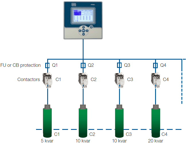
The power factor controller (PFC) is the control unit of the automatic capacitor bank system. It performs the switching of capacitors to achieve the user-defined target cosɸ. By integrating a power factor controller, it is possible to optimize the process, speed up troubleshooting and reduce the cost of the supervisory system.
The power factor controller monitors the reactive power of the power plant and tries to match the power factor value. The power factor value is defined as the ratio of active power (W) to apparent power (VA), which is defined on the device by the end-user. It has a user interface and a menu-driven plain text display for maximum ease of operation. Displaying various grid parameters, storing various values, and a test run option make it easy to analyze errors and monitor the system.
The power factor controller permanently monitors the installed reactive power and controls the power factor. Control is done by connecting and disconnecting the power capacitor bank. When the power factor decreases, the controller activates the capacitors in turn.
If the power factor is less than the approved value, the microprocessor of the controller generates a command to turn on the relay. Opening the relay will add a capacitor bank to the circuit to improve the power factor. (The capacitor increases the reactive load of the circuit, which will help increase the power factor.) The controller will continue to add the capacitor in parallel to the load until the power factor reaches a good value.
In addition to power factor correction, electrical parameters such as current, voltage, power, energy, demand, and maximum/minimum values can also be displayed. It is like the brain of the energy correction system.
The advanced PFC has the characteristics of “sequential connection” and “loop connection”. The sequential connection involves connecting and disconnecting stages in sequence (last in, first out). The power for each stage is based on its low power. A loop connection involves connecting and disconnecting stages one after another. the controller operates in loop mode (first in first out), which will minimize the wear of the capacitor bank, that is, when the sizes of the stages are equal, the stage with the longest disconnection time is always connected behind.
2. If you want to choose a power factor controller for your application, you should consider the following parameters:
- The number of capacitor banks should be considered.
- Easy to install.
- The menu should be friendly.
- It should have multiple language options.
- The power supply voltage should be wide.
- The availability of automatic and manual modes is important.
- Should not be affected by electrical harmonics.
- If communication is required, there should be communication options.
- There should be an alarm output.
- Save the parameters.
3. The following are the main advantages of the power factor controller:
- Less reactive power consumption.
- Long equipment life.
- The efficiency of the power system.
- Reduce electricity bills for households and industries.
- Fewer failures and downtime.
- Low energy consumption.
- Easy to monitor parameters.