Introduce
A relay is an electronic control device that has a control system (also called an input loop) and a controlled system (also called an output loop). Circuits for automatic control often use this component.In fact, it is an automatic switch that uses a smaller current to control a larger current. As a result, it serves as a circuit regulator, a safety circuit, and a converter. The relay has the characteristics of fast response, stable operation, long service life, and small size. In order to ensure the better performance of these performances, the testing and maintenance of the relay is particularly important. This article will introduce the main test parameters of the relay, how to test the relay, and take the test of a certain automotive relay as an example.
Test a relay
contents
introduce
1. Understanding Relay
1.1 Relay parameters
2. How to test A relay?
2.1 Overall test idea
2.2 Types of relay test
3. Relay life: automotive relay test
3.1 Automotive Relay
3.2 Common faults of automotive relays
3.3 Detection method
3.4 Specific operations
4. A question about relay test and further
4.1 Problem
4.2 Answer
5. Frequently Asked Questions about Relay Test
6. Understanding Relay
6.1 Relay parameters
The main relay parameters include rated operating voltage, rated operating current, coil resistance, contact load, etc.
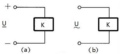
- Whena relay is operating normally, it must have a voltage that the coil requires to operate properly.For DC relays, it refers to DC voltage (Figure a), for AC relays, it refers to AC voltage (Figure b). The same type of relay usually has multiple evaluated working voltages to meet the circuit requirements, and the specification number is added to the end of the component to distinguish.
- Rated working current refers to the current required by the coil when the relay is working normally.

Relays are selected based on their rated working voltage, rated working current, and coil resistance. When selecting a relay, be sure it has the appropriate rated working voltage and current.
- Contact load refers to the load capacity of relay contacts, also known as contact capacity. JZX-10mrelay contact load, for example, is 28v*When in use, the voltage and current passing through the relay contacts cannot exceed the rated value, otherwise the contacts will be burned out and the relay will be damaged. The load of multiple sets of contacts of a relay is usually the same.
Recommended reading: Video tutorial on the basics of relay electronics The role and working principle of relays
6.2How to test A relay?
Relays are widely used in power protection, automation, sports, remote control, measurement and communication equipment, so it is very important to check and maintain the normal operation of the relay. There are many kinds of relays. Therefore, the detection of the relay cannot be judged only by measuring the resistance value of the coil. According to the different types of relays, multiple detection methods are required.
6.3 Overall test idea
1) Measuring contact resistance
Apply the specified operating voltage to the relay coil, and use a multimeter to detect the on-off condition of the contacts at the “R×1k” gear. When no power is applied, the normally open contact does not work, and the normally closed contact conducts. When the power is turned on, you should hear the sound picked up by the relay. At this time, the normally open contact is conductive, and the normally closed contact is reversed, and the switch contact should switch accordingly. Otherwise, the relay will be damaged. The remaining contacts of a multi-group relay can still function if some of their contacts are damaged.
2) Measuring coil resistance
You can use a multimeter to measure the resistance of the relay coil at the R×10Ω position to determine whether the coil is disconnected.
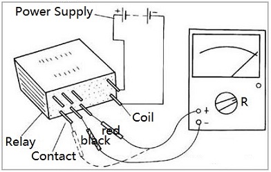
3) Measure the pull-in voltage and current
Use an adjustable regulated power supply to input a set of voltages to the relay, and connect an ammeter to the power supply circuit for monitoring. Slowly increase the power supply voltage. Take note of the voltage and current when the relay starts pulling in.To be more accurate, you can try several times to get the average value.
4) Measure the release voltage and current
Same as the test connection above. When the relay is closed, gradually reduce the power supply voltage. Try to get the average release current and voltage several times when you hear the release sound. Jot down the voltage as well as the current each time.Under normal circumstances, the release voltage of the relay is about 10-50% of the pull-in voltage. If the release voltage is too small (less than 1/10 of the pull-in voltage), it cannot be used normally, affecting the stability of the circuit and causing abnormal operation.
6.3 Types of relay test
- Electromagnetic relay test
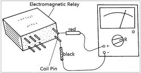 Place the multimeter on the “R×100” or “R×1k” gear, and connect the two test leads (regardless of positive or negative) to the two pins of the relay coil (as shown in Figure 5). The instructions of the multimeter should be It basically matches the resistance of the relay coil. If the resistance value is obviously too small, it means that the coil is partially short-circuited; if the resistance value is 0, In the event of an infinite resistance value, it means that the pin or coil is disconnected; a short circuit occurs between the two coil pins.
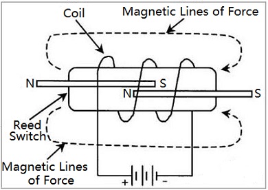
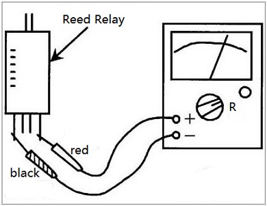
Reed relay test
Reed relays are also one of the most commonly used relays. The reed switch is made up of a coil and reed switch, as illustrated in Figure 6.The reed switch is made by sealing two non-connected ferromagnetic metal bands in a glass tube, and the reed switch is placed in a coil. When the current passes through the coil, the magnetic field generated by the coil magnetizes the metal pieces in the reed tube. The two metal pieces attract each other due to opposite polarities and connect to the controlled circuit. Several reed tubes can be placed in the coil, and they act simultaneously under the action of the coil’s magnetic field.
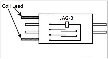
Relays are equipped with coil pins and relay switches, and most shells have corresponding marks for identification.
Reed relays can also use a multimeter to detect their coils and contacts. The detection method is the same as that of electromagnetic relays.
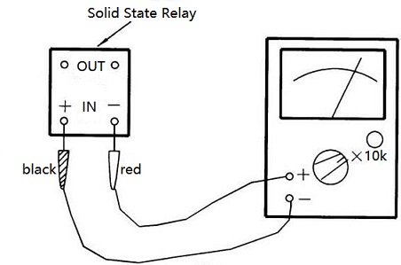
Solid State Relay (SSR) testing
The input can be tested with a multimeter. The multimeter is placed in the “R×10 k” equipment, the black test lead (the positive meter of the battery) is connected to the positive SSR input terminal, and the red test lead (that is, the negative meter of the battery) is connected to the negative input terminal of the Soviet Socialist republic. The hand should deflect more than halfway (Figure 9). Retest after exchanging the two test leads. The hands should not be moved. If the pointer deflects to the top or does not move regardless of the forward or reverse voltage access, the solid state relay has been damaged.
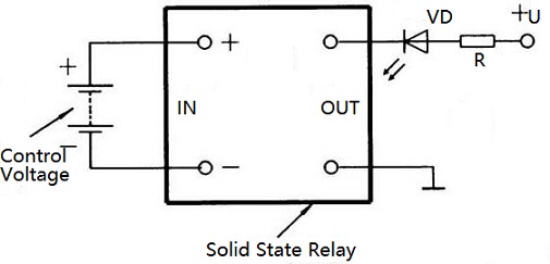
The test circuit can also be made according to Figure 10. When the control voltage at the SSR input terminal is turned on, the light emitting diode VD is turned on; when the control voltage at the SSR input terminal is cut off, the light emitting diode VD is turned off.
Thermal relay test
1) Heating element detection
The heating element is composed of an electric heating wire or an electric heating sheet, and its resistance is very small (close to 0Ω). The detection is shown in Figure 11. The normal resistance of the three groups of heating elements should be close to 0Ω. If the resistance is infinite (the digital multimeter displays “1” or “OL” symbol to indicate that the range is exceeded), the heating element is turned on.
Figure 11.
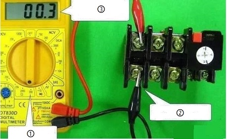
①Choose 200Ω gear.
②The red probe and the black probe are respectively connected to the two ends of the heating element.
③The resistance is close to 0Ω, indicating that the resistor is normal as a heating element.
2) Contact detection
Thermal relays usually have a normally closed contact and a normally open contact. The test includes working and non-working conditions. The first picture is the detection when the normally closed contact resistance is not working. Under normal circumstances, it should be close to 0Ω. Then test under the opposite conditions. Move the test rod, as shown in Figure 2, to simulate over-current heating and bending of the heating element to make the contacts act. Normal closed contacts become open circuits, and the resistance is infinite.
Figure 12.
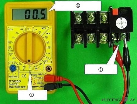
①Choose 200Ω gear.
②The red and black probes are respectively connected to the two ends of the normally closed contact.
③The resistance is close to 0 Ω, which means the normally closed contact is closed.
④ Move the test rod by hand.
⑤ The over-range symbol “1” is displayed, indicating that the normally closed contact is open.
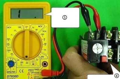
Intermediate relay test
A multimeter’s resistance gear is used for both coils and contacts of the intermediate relay.
1) The contact is detected when the control coil is not energized. Contactors include normally open contactors and normally closed contactors. When the control coil is de-energized, the normally open contact is disconnected and the resistance is infinite. At this time, the normally closed contact is closed and the resistance is close to 0Ω. The detection of the above-mentioned normally open contact is shown in the figure below.
Figure 13.
①Choose 200Ω gear.
②The red and black probes are connected to both ends of the normally open contact.
③The over-range symbol “1” is displayed, indicating that the normally open contact is not closed.
2) The detection of the intermediate relay control coil is shown in Figure 14. Generally speaking, the larger the rated current of the contact, the smaller the resistance of the control coil. This is because the larger the rated current of the contact, the larger the volume of the contact. Only a smaller control coil resistance (a thicker wire diameter) can flow a larger current and generate a stronger magnetic field to attract the contacts.
Figure 14.
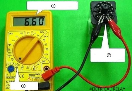
①The gear switch selects 200Ω gear.
②Connect the red and black wires to the two pins of the control coil.
③“6.60” shows that the control coil resistance is 6.6kΩ.
3) Turn on the control coil and detect the contact. Apply rated voltage to the control coil, and then use a multimeter to detect the resistance of the normally open and normally closed contacts. The normally open contact should be closed and the resistance should be close to 0Ω; the normally closed contact should be open and the resistance should be infinite.
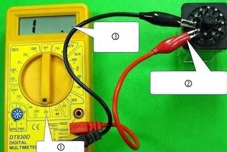
Time relay test
The detection of the time relay mainly includes the normal state detection of the contact, the coil detection and the coil energization detection.
1) Detection of the normal state of the contact. It refers to the detection of contact resistance when the control coil is not energized. Normal open contacts have infinite resistance, while normally closed contacts have close to zero resistance.The normal detection process is shown in the figure below.
Figure 15.
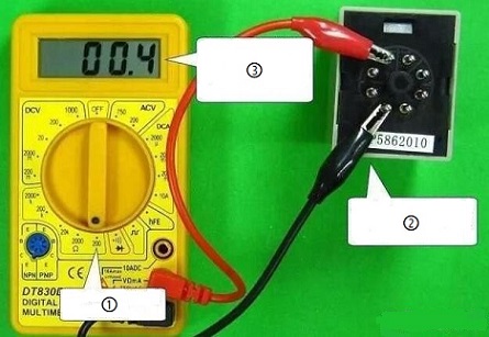
①The gear switch selects 200Ω gear.
② The red and black leads are connected to the two pins of the normally closed contact.
③The resistance is close to 0Ω, indicating that the normally closed contact is closed.
2) Control coil detection. As shown in Figure 16.
Figure 16.
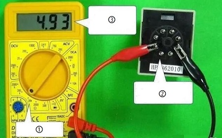
①The gear switch uses 20kΩ gears.
②Connect the red and black wires to the two pins of the control coil.
③ “4.93” means a 4.93k* resistance for the control coil.
3) Turn on the control coil and detect the contact. Test the contact status of the time relay by applying the rated voltage to the control coil.Take the delay time relay as an example. After a period of delay, check whether the delay contact is closed (resistance is close to 0Ω) and whether the delay contact is disconnected (resistance is infinite).
6.4 Relay life: automotive relay test
3.1 Automotive Relay
Basically, Relays are used in most automotive circuits due to the high current that starts the vehicle. For starters, wipers, rear window heating, and other circuits.If the ignition switch is directly controlled, the starting contact will ignite and burn, affecting the service life of the ignition switch, and even cause serious consequences such as line ablation and fire. Using relays to control large and small currents will not cause the above problems.
An electromagnetic relay coil generates magnetic flux when it is applied a certain voltage or current at both ends, which passes through the magnetic circuit consisting of the magnetic core.the yoke, the armature and the working air gap of the magnetic circuit. Under the action of the magnetic field, the armature attracts the pole face of the iron core, so that the normally closed contact opens and the normally open contact closes. When the voltage or current at both ends of the coil is less than a certain value, the mechanical reaction force is greater than the electromagnetic attraction, and the armature returns to the initial state: normally closed contact, normally open contact. One of the functions of automotive relays is switching; the second is load overload protection; the third is fault protection.
3.2 Common faults of automotive relays
Including coil burnout, short circuit, insulation part aging, contact point ablation, etc.
1) Relay failure
When the controlled circuit requires closing, the relay does not act. On the contrary, when the controlled circuit does not require closing, the relay acts. It is caused by the interference voltage in the circuit exceeding the relay drive circuit’s operating range. When designing the circuit, pay attention to the factors that may cause interference (such as chip command error, short circuit, power grid fluctuation, etc.).
2) Relay burned out
There are many reasons for job burnout. The actual switching current and inrush current exceed the rated switching current and inrush current, respectively, for the relay. According to design experience, in order to avoid these problems, the rated current should be selected to be 2-3 times the actual switching current, It is 2-3 times as strong as the actual current in the relay when it is installed.3) Contact welding
Temperature rise is generally higher for AC conversion relay coils than for DC conversion relays.This is caused by eddy current loss and hysteresis loss in the magnetic circuit. In addition, when the AC conversion relay works at a voltage lower than the rated voltage, it may jump. This will cause burnout, contact welding and relay damage, or disconnect the self-protection circuit. For this reason, it is imperative to take steps to prevent fluctuations in voltage.
In addition, regardless of the length of the fluctuation time, it will cause the failure of the relay. Make sure the power supply has enough capacity.
4) The coil temperature rise is too high
The loss of magnetic materials such as copper wires and iron cores or the heat transfer of the contacts will cause temperature rise. Therefore, special attention should be paid to the heat resistance of the insulating material and the distance between the relay and the heating device in the circuit design.
3.3 Detection method
Static detection: check the coil resistance and the normally closed contact resistance.
Dynamic detection: Energize the coil to detect the resistance of the normally open contact.
3.4 Specific operations
- Turn on the ignition switch, listen for the pull-in sound of the control relay or feel the relay vibrate with your hands. If so, it means that the relay is basically routine. Circuit failure may be caused by other reasons. On the contrary, this means that the relay is faulty.
- Replace the relay to be tested with the same working relay. Inthe case of an electrical issue, if the switch is turned on and the equipment works, it is possible to determine that the relay is malfunctioning. Use a multimeter Rx100Ω gear and analyze the resistance of each pin of the circuit. If the conduction and disconnection are normal, there is no problem with the relay, otherwise the relay is faulty.
- Open the relay case and check whether the contacts are ablated or oxidized. If there are bumps and rust on the contact point, it means that the contact point is ablated or oxidized and cannot work normally.
- Check whether the coil is ablated or discolored. If the coil is ablated with jelly, the coil is black or has a gluey smell, which means that the coil is short-circuited and ablated.
ⅣA question about relay test and further
4.1 problem
What are the symptoms of a bad relay race?
4.2 answer
The car stopped abruptly when it started. One of the most common symptoms of ignition relay failure is that the car suddenly stops while it is running.
The car does not start. Another symptom of a malfunctioning ignition relay is a no-power state.
Dead battery. A dead battery is another symptom of a malfunctioning ignition relay.
Burning relay.
6.4 Frequently Asked Questions about Relay Test
1)How to check if the relay is broken?
Multimeters are the only tools required to test the relay.When the relay is removed from the fuse box, the multimeter is set to measure the DC voltage, and the switch in the cab is activated. First, check whether the 85 positions (or the position where the relay is located) where the relay is inserted in the fuse box have 12 volts.
2)How to test a 12 volt relay?
3)How to check the overload relay with a multimeter?
CEP7 overload relay test program
Measure the normal operating current of the motor (i motor).
Turn off the motor and let cool for about 10 minutes.
Calculate the following ratio: i(motor)/i(overload minimum FLA).
Set the overload to the minimum FLA, and then turn on the motor.
Wait for the overload situation to occur.
4)How to test solid state relays?
If a load is connected, the SSR can be tested as described below. Connect the load and the power supply, and check the load terminal voltage with the input ON and OFF. When the SSR is off, the output voltage will be close to the load supply voltage.
5)Will a bad relay drain your battery?
Dead battery or dead battery
A failed ECM power relay can also cause battery drain or battery drain. If the relay is short-circuited, it can keep the computer’s power on even when the vehicle is turned off. This will form parasitic leakage on the battery and eventually lead to battery failure.
6)What should I do if the main relay is broken?
The engine won’t start
It is impossible for the engine to crank and run correctly if the main relay isn’t providing the computer with the power it needs. If the main relay cannot be replaced, it usually renders the car unusable.
7)How to test the battery relay?
8)How to test the protection relay?
Protection relay self-check program
This usually includes checking the relay watch circuit, performing all digital inputs and outputs, and checking whether the relay analog input is within the calibration range by applying a test current or voltage.
9)How to check if the relay is working?
Only a multimeter is required to test a relay.
A multimeter is all that’s required for testing the re
When the relay is removed from the fuse box, the multimeter is set to measure DC voltage, and the switch in the cab is activated. First, check whether the 85 positions (or the position where the relay is located) where the relay is inserted in the fuse box have 12 volts.
10)How to test electromagnetic relay?
Take a multimeter and set it to ohms. Touch the wire on the solenoid coil pin and measure the resistance. Any place between 50-120 ohms is fine. Out of range or opening means a bad solenoid coil winding and time for a new relay.