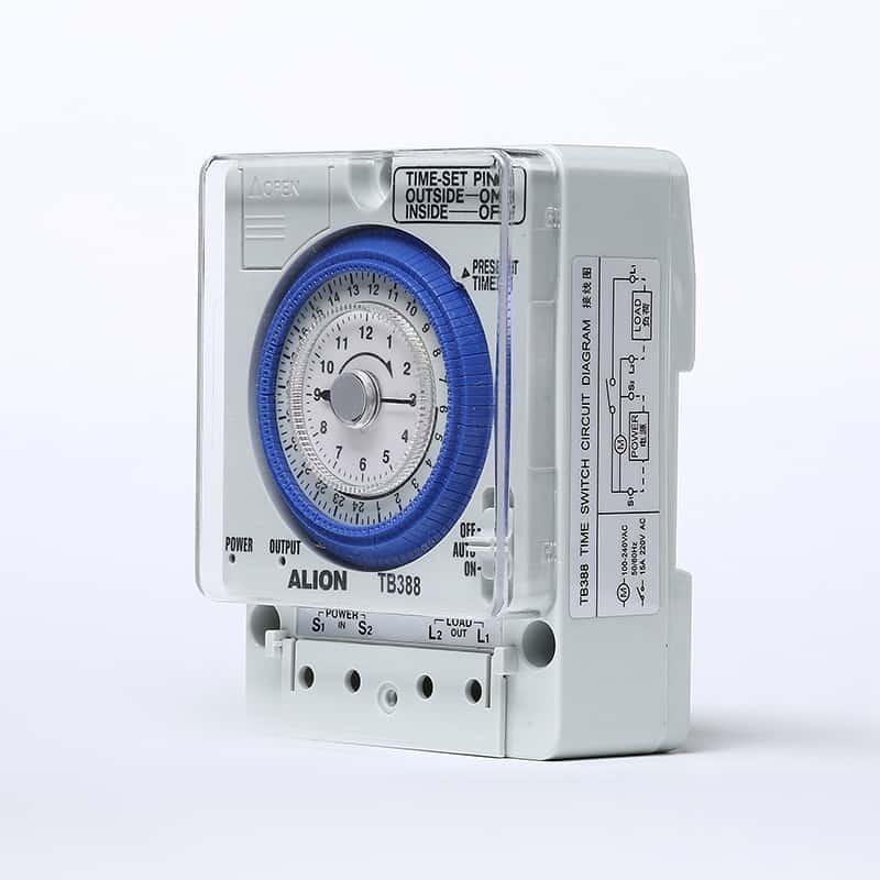
Both contactors and relays can be best defined as live devices to manage and maintain the efficiency of the circuit. Usually, the arc is supported by an air contactor and a series of similar tools for this purpose.
It is often difficult to distinguish between relays and contactors since they are located on a single control panel. So, what are the specific characteristics of electrical contactors and relays? What are the working principles of contactors and relays? Well, we will find the answers to these questions in the next few sections.
1. Introduction to Contactors and Relays
The characteristic of electrical contactors and relays is that they work on the same principle. In the simplest terms, the above two devices are electromagnetic switches that adjust and manage electrical loads through further charging. Their structure is almost the same, which further supports many similarities in their working principles.
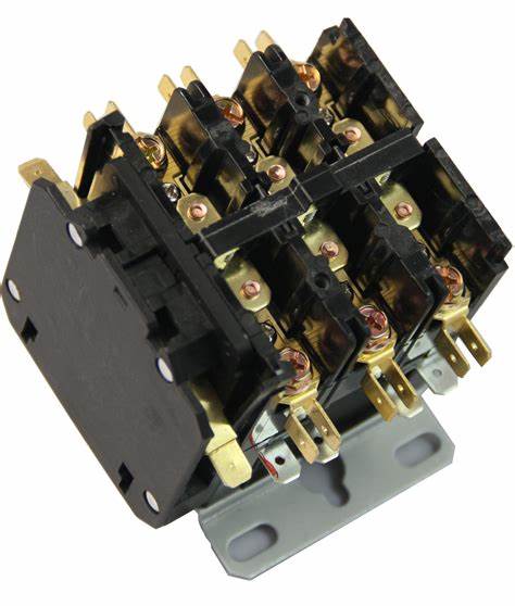
What does a contactor or relay do? And how are contactors and relays made?Both devices have a top housing and a bunch of contacts. Note that these contacts are usually open, although they may also be closed. Different from the top shell, there is an excellent magnet and coil at the bottom of the shell of these two devices to continue to maintain and protect the other third accessories.
2. How do relays and contactors differ?
Now that you have a clear understanding of the working principles of relays and contactors, you may be wondering what are the key differences between these devices. The main difference between these two devices is the current rating they maintain. Since contactors are used to handle high-voltage and high-current electrical loads, they are often significantly different from ordinary relays.
In order to better understand the difference between these two devices, please review the following feature definitions that outline the role and purpose of the device.
Function
The best definition of a control relay is a product that can ensure that all contacts in a specific circuit can operate successfully even when the conditions of the same or similar circuit change.
On the other hand, a contactor is a device designed to interrupt an existing circuit in a normal environment.
Size
The key difference between these two products is their size. Compared with the contactor, the volume of the control relay is quite small. Secondly, because of this small capacity, the control relay carries less load than the contactor.
3. Electrical load and circuit range
Contactors are most suitable for carrying loads higher than 10A, while control relays can only carry loads up to 10A. This is why, you usually find that the control relay system operates in a single-phase circuit, mainly in the control circuit, and the contactor can effectively manage the three-phase electrical load.
4. Type of contact
Another related difference between relays and contactors is the auxiliary contacts of the device. When you find in a contactor that there are at least three electrical contacts with some additional built-in contacts, an average control relay will only contain two non- or NC type electrical contacts. Similarly, when you find that a control relay has both open and closed contacts, the typical contactor is adjusted to operate only when the contact is open. Unlike relays, they operate on type A contacts.
5. System rating
As mentioned earlier, the final and biggest difference between these two devices is their system ratings and voltage control capacity. The rated voltage of traditional relays is only 250v, while the rated voltage of contactors is usually 1000 V or higher.
It should be noted that the biggest difference between these two devices is their size and structural features. Relays are much smaller than contactors, which is why when you compare them to contactors, their functions, voltage, and capacity are often limited. Since these two devices have different functions, you cannot use them interchangeably.
6. Application of relays and contactors
It can be seen from its structure that both relays and contactors have specific functions. For example, relays are designed for single-phase circuits, and they are best suited for single-phase applications. Or, you may want to use contactors in a grid with at least three phases. Although the functions of the modern torch relay differ due to its many characteristics, some basic applications include:
- Automotive equipment
- Manage and monitor motors
- Several industrial applications
7. Manage and control electrical loads
Like relays, contactors have a series of categories, although you will find that they have several uses. The basic operations include:
- Start the motor
- Switch existing capacitor banks
8. Control and monitor lighting equipment
How to choose a contactor or relay?
If you are confused about choosing a contactor or relay, you may need to consider the following pointers:
The control relay is most suitable for the operation of single-phase circuits that require 250 VAC and a current capacity of 10a or less.
Or, when the current capacity is 9A or higher, you may want to use a contactor in a single to a three-phase circuit with a capacity requirement of 1000 VAC or higher.
Once these key factors are considered, it is easier to determine which of these two devices best suits your needs. As mentioned earlier, since both devices have specific and single functions, it is best to use the appropriate product in the appropriate environment.
Conclusion
You may want to use contactors to switch motors or lighting fixtures or any other known high-capacity current equipment. These devices also have at least one pair of specific contacts in the three-phase input-output capacity. The contacts are open, and in some cases, they are divided into more groups, namely auxiliary contacts with NO and NC capacities.
On the other hand, relays have only one or two pairs of open or closed contacts. You can choose to open or close the contacts just by twisting the coil. Because these two devices have different functions, it is best to operate them only within their required capacity range.
